

by John P Scott
Window - Viewport Transformations
 Introduction
Basic Window-Viewport Transformation
Isotropic and Non-Isotroptic Transformations
W-V Procedure in Pascal
Exercises
Introduction 

We are now accustomed to working with co-ordinates which are in display space. However, we know that the display is being used to represent world phenomena. e.g. a drawing of a new building. Such real world objects are not measured in units which map easily to display space. Real world data may use real numbers. The measurements may be very large (e.g. for maps) or very small (e.g. for molecular structures). This means we must convert the data to a system of measurement which puts the information on the display. This can be done on an ad hoc basis, but this would mean that we have to code our applications specifically for each case. The accepted method for handling the conversion of real world co-ordinates into display co-ordinates is through the use of a Window - Viewport transformation. The concept is quite straightforward; we define a rectangle in the real world which usually encloses the object for display. This is called the Window. We then define a Viewport on the display which is going to be used to display the windowed area of the real world. In practice, we must provide an efficient method of converting a real world co-ordinate into its display co-ordinate so that the display process is not slowed down. Figure 1 shows the scenario for this process.
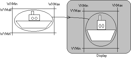
Figure 1
Basic Window-Viewport Transformation
Notice that the real world window in Figure 1 is not similar to the display viewport and so the ship has been distorted. The transformation is non-isotropic. This is possible for all Window - Viewport transformations, but in certain cases it would be undesirable to distort the real word image. In this case an isotropic Window - Viewport transformation would be required which preserves the aspect ratio of real world space. Mathematically, a Window - Viewport Transformation is quite simple and Figure 2 shows the way in which it can be calculated. You will see it is very similar to the clipping calculation. The mathematical solution can be used, but there are reasons why it would not be used in practice, which you will see when we come to consider transformations in general.
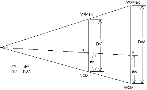
Figure 2
Isotropic and Non-Isotroptic Transformations
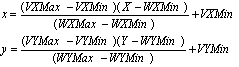
Let the real world co-ordinate be represented by (X, Y) and its equivalent co-ordinate in display space be (x,y). The formula for the non-isotropic Window - Viewport transformation is:
The isotropic transformation is slightly complicated by the need to make sure the scaling of the object is equal in both x and y. The scale factors for the transformation are given by the terms:
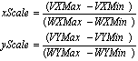
This means that the original equations must be modified using the scale factor which is the smaller of xScale and yScale, otherwise the real world window will not fit totally within the display space viewport.
W-V Procedure in Pascal
Figure 3 gives the code for the handling Window - Viewport transformations, assuming that the real world co-ordinate system is integer based.
PROCEDURE GetScale(VAR Num, Denom: Integer);
BEGIN
IF LongInt(VXMax - VXMin)*(WYMax - WYMin) >
   LongInt(VYMax - VYMin)*(WXMax - WXMin) THEN
  BEGIN
  Num := (VYMax - VYMin);
  Denom := (WYMax - WYMin)
  END
ELSE
  BEGIN
  Num := (VXMax - VXMin);
  Denom := (WXMax - WXMin)
  END
END;
PROCEDURE SetWindowViewport
  (WX1, WX2, WY1, WY2, VX1, VX2, VY1, VY2: Integer);
BEGIN
WXMin := WX1; WXMax := WX2; VXMin := VX1; VXMax := VX2;
WYMin := WY1; WYMax := WY2; VYMin := VY1; VYMax := VY2;
XNum := (VXMax - VXMin);
XDenom := (WXMax - WXMin);
YNum := (VYMax - VYMin);
YDenom := (WYMax - WYMin)
END;
PROCEDURE IsotropicSetWindowViewport
  (WX1, WX2, WY1, WY2, VX1, VX2, VY1, VY2: Integer);
BEGIN
WXMin := WX1; WXMax := WX2; VXMin := VX1; VXMax := VX2;
WYMin := WY1; WYMax := WY2; VYMin := VY1; VYMax := VY2;
GetScale(XNum, XDenom);
YNum := XNum;
YDenom := XDenom
END;
PROCEDURE WVTransform(VAR X, Y: Integer);
BEGIN
X := LongInt(XNum)*(X - WXMin) DIV XDenom + VXMin;
Y := LongInt(YNum)*(Y - WYMin) DIV YDenom + VYMin
END;
Figure 3
Exercises
1. Implement the Window - Viewport transformation procedures above and write a test program to show them in use, using both isotropic and non-isotropic transformations.
2. Modify the program from exercise one to allow clipping to the viewport (using your program from the previous section) so that if you ask for a line to be drawn which is outside the Window boundary it only displays the visible portion in the viewport.
Copyright (C) 1995

JPS Graphics, ******************
All rights reserved

Comments to author: *********************
